 How Long Is Your Lens?
Equations are given to compute the focal length of a lens without the need to make any measurements on the lens itself, if the spacing between pixels on the sensor is known.
 How Long Is Your Lens?
Recently, I had a project where I needed to know the focal length of the lens I was using. This brought an unexpected lesson in two related topics. One was the difference between a true zoom lens and a varifocal lens. The other was that "focal length" is a casual specification for the lens I was using.
 When we work with lenses, it would be ideal to consider a lens as thin as
possible, like the one on the left. All of those textbook equations from
high-school physics work. To change focus, just move the lens back and forth
a bit. To zoom, find some magic to change its curvature. It will have to
move a bit so focus is preserved, but that looks fairly straightforward.
 The lens designer is not so fortunate. She must deal with materials that
don't squeeze well, and with several kinds of aberrations. The result is a
nightmare like we have at right, a diagram of a modern zoom lens. That one
is a cutaway of a popular 18-70mm kit lens. Instead of changing the
curvature of an ideal element, fifteen elements are repositioned within
the
whole assembly to change the focal length. More repositioning changes the
focus. It's extremely hard to keep all of this synchronized, so
photographers have got used to the idea that we need to refocus when changing
the zoom.
One unfortunate side effect of all this is that, when these interactive zoom and focus operations are complete, the actual focal length of the lens isn't always what we think it is. This brings us into the realm of focus breathing, the subject of more discussion than this article can afford to address. It rarely matters, because the photographer subconsciously adjusts for the error while composing the picture. But if you want to use the resulting picture to measure something in it, it matters a lot.
This article presents two ways to compute focal length if you don't have an optical bench. One is suitable for typical indoor work, where the focus is not on infinity. The second method works outdoors, where the focus may safely be assumed to be infinite – but you need to know the angle between two points in the picture, which is easier said than done.
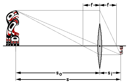
We can still use those thin-lens equations to analyze the problem, but we have to deal with the location of that ideal thin-lens plane It's somewhere within (or at least near) that complicated group of elements in the real lens, but we don't know exactly where. Fortunately, we don't have to know, if we know where the object and the image (i.e., the sensor) are. Here's a typical thin-lens diagram, with the addition of s, the total distance between object and sensor.

The object and image distances from the (unknown) lens plane are related by the thin lens equation:
Two things that we can measure are the magnification and the distance between the object and its image.
Combine Eqs. 1 and 2 to eliminate si
Do the same with Eqs. 2 and 3:
Then we can combine Eqs. 4 and 5 to an expression that has only one unknown quantity (f), plus two things we can measure.
Solving for f,
— the desired relation, whereby focal length can be derived from two available quantities. All you have to do is take a picture of a ruler from a known distance.
 I did that, placing the focal plane 113 inches from the wall where the ruler
was fastened (it just worked out that way). On my camera, you can drop a
line from the lens mounting flange that clears the tripod, and the
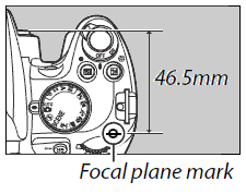
manufacturer tells how far this is from the sensor plane. Obviously, it's
still imprecise. I'll cover this uncertainty in due course.
So, the object-to-image distance is
By using a ruler, we definitely know the size of the object. The size of the image is measured in pixels, so we also need to know the size of one pixel. For the APS-C sensor in this camera, published pixel pitch is δ = 5.5 μm.
So the magnification can be calculated from simple dimensional analysis.m = a pixels/inch · δ mm/pixel · 1/25.4 inch/mm

This is the center part of the photograph of the ruler (the full photo is here), showing 419 pixels between the 46 and 50-inch marks, or about 105 pixels per inch. For better precision, I plotted the range from 34 to 60 inches on the ruler, arriving at this relation:

from Eq 8.
Now that we have values for s (Eq. 7) and m (Eq. 9), we can substitute them into Eq. 6 to find the focal length:
f = 0.02284 × 2870 / 1.022842 = 63 mm
Note that you can't rely on EXIF metadata here. The EXIF data in the image used for this discussion indicates the focal length as 70.0 mm. If you used that number for any measurements, you'd be off by about 10%.
The error analysis that follows is well beyond the scope of this article. Almost every reader will want to skip to the next section.
The accuracy of the focal length as calculated by Eq. 6 is mainly affected by the precision in the pixel pitch δ. So long as the object-image distance is known within an inch or so, it doesn't affect the result much. Even with these errors at their worst, Eq. 6 yields the actual focal length within 1 mm.
It's natural to wonder how sensitive this derivation might be, to the relatively casual setup of this experiment. In particular, we don't know the object-image distance s as well as we'd like, and the pixel pitch δ is only known to two significant figures. We can put some numbers to this, but it requires a bit of calculus. Restating Eq. 6, the focal length is
If we have a good handle on the error in the distance s and magnification m (directly related to the error in pixel pitch), we can state the error in derived focal length as
Let's take a closer look at the components of Eq. b for the parameters that were used for the 70mm lens, assuming we only know the object-image distance to the nearest inch. All we know about δ is that it's most likely between 5.45 and 5.55 μm; i.e., dδ =0.05μ. The next four equations will assign numbers to the components of Eq. b for this case.
Putting it all together,
A bit of experimenting in an Excel spreadsheet shows that this determination is more sensitive to dδ, the uncertainty in pixel pitch, than anything else; but even that doesn't matter a whole lot. For lack of better information, I assumed pixel pitch was accurate within 1% because the most reliable number I could find was given only to two significant figures. Reducing this error to 0.1%, or even to zero, changed df to 0.6 mm. Better accuracy in locating the sensor plane only helps a little bit; if the position is known within ½ inch, df goes from 1.1 to 0.8 mm. If we could make both improvements, df is reduced to 0.3 mm.
As the object-image distance increases (moving from portraiture to landscape photography), the error gets smaller. Here, we'd be interested in what happens to the elements of Eq. b in the limit as s >> f, or m->0. Eq. d shows that ∂f/∂s->0, so we are only concerned with the first addend in Eq. b. Consider the terms in brackets in Eq. c:
Substituting this into Eq c, and then into Eq. b,
If dm is expressed as a fraction κ of m, if s >> f we can say
where it doesn't really matter if f represents the nominal or calculated focal length; it's the percentage that's interesting. With a little thought (and another look at Eq. e), we realize that we can't calculate f to any better precision than we know the pixel pitch δ.
If the object is far enough away, the lens will focus on infinity. In terms of the thin lens equation (Eq. 1),
– and the geometry looks like the next figure. Note that the object distance isn't represented. We don't need it, if we know the angle subtended by two points in the picture. For example, we might have a reference picture with two landmarks whose latitude and longitude are known, and also know the coordinates of the camera location. This is enough information to determine the angle labelled α in the figure, but it requires spherical trigonometry. Let's just say it's not impossible. There's a calculator at the end of the Google Maps section.
In another article, Bob Atkins describes how to use a night sky shot to read the angle between two bright stars.

Try to center your reference points in the test picture, so the calculation will be as accurate as possible. Ideally, the reference points and the center of the theoretical lens plane will form an isosceles triangle. If we consider half of this triangle (a right triangle),
Rearranging that equation (h = n δ),
where
Eq. 10 can be simplified a bit, if the angle α is small enough. For small angles, tan(θ) ≅ θ, where θ is in radians. The error in this assumption is
Making that substitution in Eq. 10,
– or, for α in degrees,
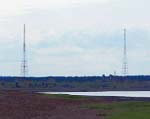
 There is a pair of radio antennas
two miles from a convenient location for the
camera. That's definitely far enough to get the lens to focus on infinity.
From that vantage point, the antennas are about three degrees apart.
Running this analysis on the same 18-70mm lens as used earlier in the
article, Eq. 11 gave its actual focus range as 18 to 69 mm. Not
bad.
The same kind of differential analysis as used previously leads again to the conclusion that uncertainty in the pixel pitch is the dominant factor. Specifically,
where one term has been eliminated because it is assumed that the subtended angle is known to much greater precision (< 0.1%) than the pixel pitch (1%). That is
for the APS-C sensor that has been used for the examples here. By way of example, for objects that are 5° apart and separated by 2000 pixels in the image, Eq. i shows the uncertainty in focal length to be about 1 mm, or the same as before.
There is a common problem among people who use digital calculators without
understanding the difference between precision and accuracy.
In any set of calculations, we need to be careful about significant figures.
A measurement is never better than half of its last decimal place. That is,
"1 inch" is a different animal from "1.234 inch" or even
"1.000 inch". "1 inch" means anywhere from 0.5 to 1.5 inches,
whereas "1.000 inch" means
The limiting factor in the calculations for this article's APS-C sensor is the pixel pitch, given as 5.5 microns. Two significant figures. Any result should be constrained to the same; so if a calculation says the focal length is 57.14159265 mm, it should be reported as 57 mm. We just don't know it any better than that.
Fortunately for this exercise, it's usually good enough to know the focal length to one-millimeter precision.
 Speaking of significant figures,
Google Maps has a great
feature, but I wonder how far to trust it. If you right-click on the map,
select "What's here?" from the context menu that pops up. The browser will
then show a little layer that gives the latitude and longitude of the place
where the mouse was for the right-click – to six decimal places!
That's ±5×10⁻⁷ degree on the surface of the Earth, or
about two inches.
This is Google's satellite view, zoomed-in as far as it will go,
locating one of the points on Lady Liberty's crown. As you can
tell from the scale bar at lower right, 20 feet corresponds to 108 pixels on
this display. Each pixel is 2.2 inches
square. If the registration is really that accurate (and if the Earth were a
sphere), that is truly remarkable.
For this project, I plotted a few locations this way and used them to
calculate compass bearings, but not to two-inch precision. Accuracy of a few
feet – an order of magnitude larger – was just fine to get the
subtended angle needed for Eqs. 10 and 11.
Here's a calculator to find the angle the camera sees between two points on the map. Enter the coordinates in the decimal degrees, same as used by Google Maps. South latitudes and west longitudes are negative numbers.

First method (object is a few feet away)
Second method (distant object)